Table of Contents
- Introduction
- Vehicle input data
- Charging input data
- Battery cell input data
- Battery cell results
- Battery pack results
Introduction
The sizing of a high voltage battery pack for electric vehicle (EV) applications is an important factor in determining the performance and efficiency of the vehicle. The following are the key steps in the process of sizing a high voltage battery pack:
- Determine Energy Requirement: The first step is to determine the amount of energy that the battery pack needs to store, based on the driving range desired, the vehicle's power consumption, and other factors.
- Calculate Capacity: The next step is to calculate the capacity of the battery pack in kilowatt-hours (kWh), which is the amount of energy that can be stored and used.
- Select Battery Cells: Based on the calculated capacity, the type of battery cells to be used is selected. The choice of battery cells depends on the energy and power requirements, cost, safety, and other factors
- Determine Pack Configuration: The number of battery cells, the arrangement of cells in the battery pack, and the wiring configuration are determined based on the desired voltage and current requirements.
- Calculate Pack Dimensions: Based on the selected battery cells and the pack configuration, the dimensions of the battery pack are calculated, including its volume, weight, and physical size.
- Evaluate Performance: The final step is to evaluate the performance of the battery pack, including its energy and power density, safety, and efficiency, to ensure that it meets the desired requirements and specifications.
This calculator can be used to size battery packs for electric vehicles (EVs), for different types of battery cells and taking into account the vehicle's performance data.
By displaying the battery parameters in table form and bar chart form, for different types of battery cells, the user can decide which battery cell is most appropriate for their application.
The process of sizing a high voltage battery pack for EV applications involves a complex trade-off between cost, performance, safety, and other factors, and requires careful consideration of multiple factors to ensure the best possible solution.
Vehicle input data
The battery pack is sized mainly function of the expected range of the vehicle and power output requirements.
The input parameters related to the vehicle are:
- Lrange [km] - the expected range of the vehicle (e.g. 250 or 350 km)
- Eavg [Wh/km] - the average energy consumption of the vehicle; this parameter can be set function of similar vehicles or can be determined using the EV performance and range simulation application. (e.g. 160 - 200 Wh/km)
- Upack [V] - the nominal voltage of the battery pack (e.g. 400 or 800 V)
- Nadd [-] - this parameter adds additional strings of cells connected in parallel, in order to increase the output current of the battery pack (e.g 0-10); if this parameter is set to 0, the number of battery cell strings connected in parallel will only be calculated function of the battery pack energy and string energy
- Rmass [-] - this parameter defines the ratio of battery cells mass relative to the total battery pack mass; for example, if set to 80 %, it means that the battery cells are having 80 % of the total battery pack mass, the remaining 20 % being taken by frames, casing, wires, circuit boards, etc.
- SOCmin [%] - minimum allowed state of charge (SOC) of the battery; this parameter is used to calculate the battery energy, required for the expected range
- SOCmax [%] - maximum allowed state of charge (SOC) of the battery; this parameter is used to calculate the battery energy, required for the expected range
- η [%] - overall efficiency, from battery pack to wheels; this parameter includes the inverter, electric motor and driveline efficiency
Charging input data
The battery pack can be charged either with AC or DC (fast charging). The table below contains a summary of the most common charging power levels.
| Charging Power [kW] | Phase | Current [A] | Voltage [V] | Type |
| 1.2 | 1-φ | 10 | 120 | AC |
| 2.2 | 1-φ | 10 | 220 | AC |
| 3.3 - 22 | 1-φ or 3-φ | 16 - 80 | 240 | AC |
| 43 - 350 | 3-φ | 63 - 500 | 400 - 1000 | AC |
| 50 - 350 | NA | 80 - 500 | 200 - 1000 | DC |
The charging efficiency of an electric vehicle (EV) refers to the percentage of energy that is delivered to the EV battery during the charging process, relative to the total energy that is drawn from the power grid or other power source. The charging efficiency can be affected by a variety of factors, including the type of charging (AC or DC), the charging power level, and the specific EVSE and electric vehicle being used.
In general, DC charging tends to be more efficient than AC charging, due to the use of a direct current that bypasses the AC-to-DC conversion process that is required for AC charging. According to some estimates, the average charging efficiency for DC fast charging is around 85-90%, while the average efficiency for Level 2 AC charging is around 70-80%.
The input parameters related to charging are:
- Pchg [kW] - charging power (see table above)
- ηchg [%] - charging efficiency (70-80% for AC and 85-90% for DC)
Battery cell input data
The battery cell input data can be obtained from the data sheet published by the manufacturer.
For example, for the battery cell INR21700-50E, manufactured by Samsung SDI, the parameters are extracted from the following table:
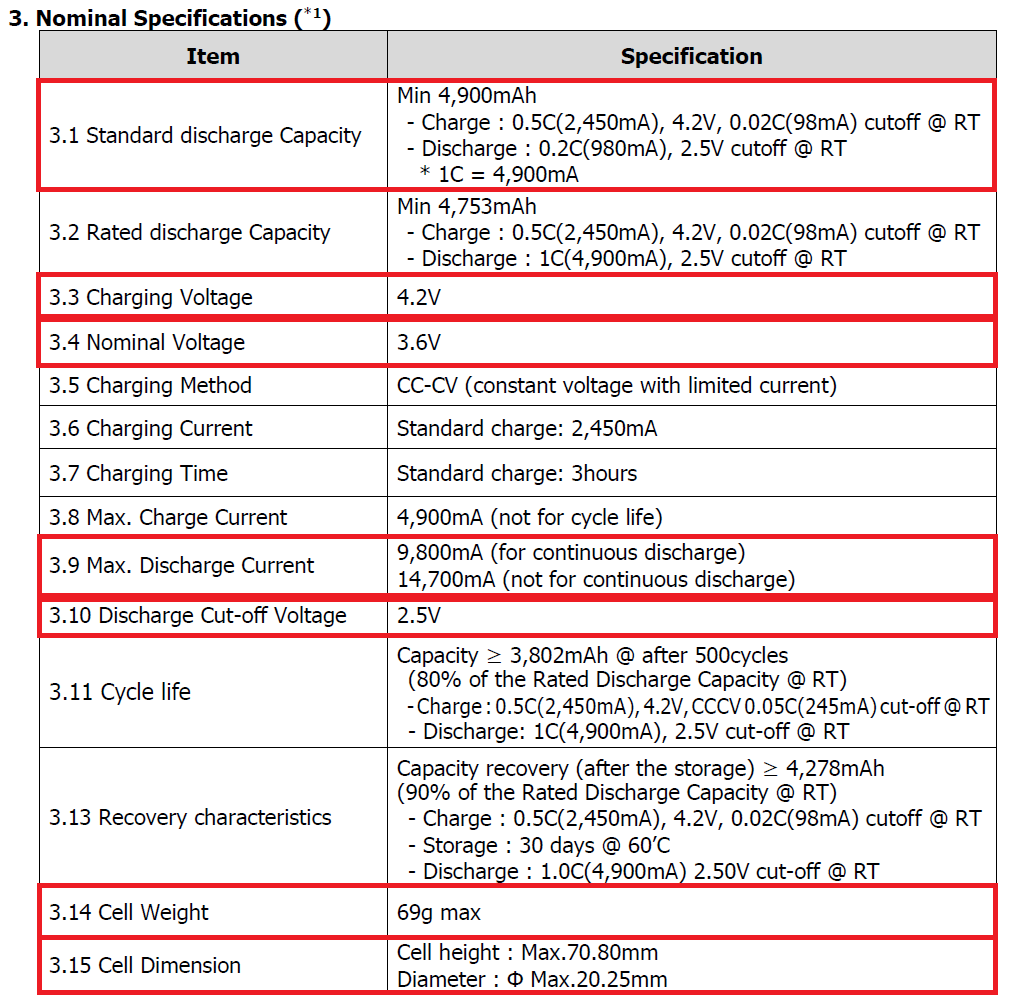
The complete data sheet (product specification) of the Samsung SDI INR21700-50E cell can be found here.
For cylindrical cells the size is specified as Diameter x Height. For pouch or prismatic cells, the size is specified as Width x Height x Depth.
Battery cell results
The equations for the cell performance data are displayed in the table below.
| Performance data | Equation | Parameters description |
| Cell volume | cylindrical cell \(V_{cell} \text{ [L]} = 10^{-6} \cdot \frac{\pi \cdot D^{2}}{4} \cdot H\) |
D [mm] - diameter H [mm] - height |
| pouch/prismatic cell \( V_{cell} \text{ [L]} = 10^{-6} \cdot W \cdot H \cdot D \) |
W [mm] - width H [mm] - height D [mm] - depth |
|
| Cell energy | \( E_{cell} \text{ [Wh]} = C_{cell} \cdot U_{cell} \) | Ccell [Ah] - nominal capacity Ucell [V] - nominal voltage |
| Volumetric energy density | \( U_{vol} \text{ [Wh/L]} = \frac{E_{cell}}{V_{cell}} \) | Ecell [Wh] - cell energy Vcell [L] - cell volume |
| Gravimetric energy density | \( U_{grv} \text{ [Wh/kg]} = \frac{E_{cell}}{m_{cell} \cdot 10^{-3}} \) | mcell [g] - cell mass |
| Power losses | \( P_{loss} \text{ [W]} = R_{int} \cdot I^{2} \) | Rint [Ω] - cell internal resistance I [A] - cell nominal current (1C) |
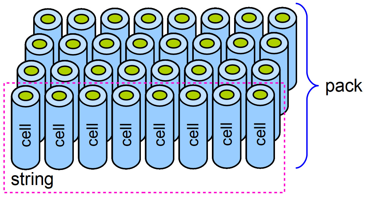
Battery pack results
The cells are arranged in series and parallel in order to output the battery pack nominal voltage and energy. The figure below shows a basic arrangement of the battery cells in a battery pack and the agreed naming convention.
The equations for the battery pack performance data are displayed in the table below.
| Performance data | Equation | Parameters description |
| Global battery pack efficiency | \( \eta_{pack} \text{ [-]} = \frac{\eta \cdot (SOC_{max}-SOC_{min})}{10^{-4}} \) | η [%] - overall efficiency SOCmax [%] - maximum allowed SOC SOCmin [%] - minimum allowed SOC |
| Battery pack energy for range | \( E_{range} \text{ [kWh]} = 10^{-3} \cdot \frac{L_{range} \cdot E_{avg}}{\eta_{pack}} \) | Eavg [Wh/km] - cell energy Lrange [km] - cell volume |
| Number of cells in series (per string) |
\( N_{s} \text{ [-]} = \frac{U_{pack}}{U_{cell}} \) | Upack [V] - battery pack nominal voltage Ucell [V] - battery cell nominal voltage |
| Battery string energy | \( E_{string} \text{ [Wh]} = N_{s} \cdot E_{cell} \) | Ecell [Wh] - battery cell energy |
| Number of strings in parallel | \( N_{p} \text{ [-]} = \frac{10^{3} \cdot E_{range}}{E_{string}} + N_{add} \) | Nadd [-] - additional strings in parallel |
| Battery pack capacity | \( C_{pack} \text{ [Ah]} = N_{p} \cdot C_{cell} \) | Ccell [Ah] - battery cell capacity |
| Total number of battery cells | \( N_{t} \text{ [-]} = N_{s} \cdot N_{p} \) | (see above) |
| Battery pack energy | \( E_{pack} \text{ [kWh]} = 10^{-3} \cdot N_{t} \cdot E_{cell} \) | (see above) |
| Battery pack continuous current | \( I_{packCont} \text{ [A]} = N_{p} \cdot I_{cellCont} \) | IcellCont [A] - battery cell continuous current |
| Battery pack peak current | \( I_{packPeak} \text{ [A]} = N_{p} \cdot I_{cellPeak} \) | IcellPeak [A] - battery cell peak current |
| Battery pack continuous power | \( P_{packCont} \text{ [kW]} = 10^{-3} \cdot U_{pack} \cdot I_{packCont} \) | Upack [V] - battery pack voltage |
| Battery pack peak power | \( P_{packPeak} \text{ [kW]} = 10^{-3} \cdot U_{pack} \cdot I_{packPeak} \) | (see above) |
| Battery pack mass | \( m_{pack} \text{ [kg]} = \frac{N_{t} \cdot m_{cell}}{10 \cdot R_{mass}} \) | mcell [g] - battery cell mass Rmass [%] - ratio of battery cells mass |
| Battery pack minimum voltage | \( U_{pack_{MIN}} \text{ [V]} = U_{cell_{MIN}} \cdot N_{s} \) | UcellMIN [V] - battery cell minimum (cut-off) voltage |
| Battery pack maximum voltage | \( U_{pack_{MAX}} \text{ [V]} = U_{cell_{MAX}} \cdot N_{s} \) | UcellMAX [V] - battery cell maximum (charging) voltage |
| Battery pack internal resistance | \( R_{pack} \text{ [}\Omega \text{]} = \frac{R_{int} \cdot N_{s}}{N_{p}} \) | Rint [Ω] - battery cell internal resistance |
| Battery pack power losses | \( P_{pack_{LOSS}} \text{ [W]} = R_{pack} \cdot I_{packCont}^{2} \) | (see above) |
| Battery pack efficiency | \( \eta_{pack} \text{ [%]} = \left( 1 - \frac{P_{pack_{LOSS}}}{P_{packCont}} \right) \cdot 100 \) | (see above) |
| Charging time | \( T_{chg} \text{ [h]} = \frac{E_{pack}}{P_{chg} \cdot \eta_{chg} \cdot 10^{-2}} \) | Pchg [kW] - charging power ηchg [%] - charging efficiency |
Observation: After calculation, the value for each parameter is rounded to the nearest upper integer.